PCB Layout

Proteus PCB design seamlessly combines Schematic Capture and PCB layout to provide a powerful, integrated and easy to use suite of tools for professional PCB Design

Proteus
PCB Layout

Product Range Overview

The Proteus PCB Design product range is a professionals choice for modern PCB Layout. With over 25 years of continuous development and innovation, our focus remains on adding functionality while maintaining a simple, clean user interface and tight integration with the schematic design.

All Proteus PCB products include a rich set of core functionality, with more advanced features being added in the higher product levels (PCB Level 2 and above). These are discussed further in the topics below.

Design capacity also scales with the product range, from a 500 pin limit in the PCB Design Starter Kit to unlimited design capacity in the PCB Design Level 3 and the Platinum products.

This flexibility in product configuration lets you choose the Proteus product that is right for you.

Footprint Libraries

Bus

The supplied libraries cover a large range of through hole components including all the most common IC, transistor, diode and connector packaging types. We also supply as standard the full IEC libraries and SMT footprints which include all the standard discrete and IC packaging styles. Both the IPC-782 and the IPC-7351 standard surface mount standard libraries are included.

If required, new packages can easily be created directly on the drawing and general 2D drafting features are also supported. A direct import tool for PADS ASCII Layout format allows footprints to be brought in from popular tools such as PCB Library Expert and Ultra-Librarian.

Templates and Technology Data

Skjema

The Proteus layout module includes a comprehensive scheme for design re-use in the form of board templates and technology data. A user can create several templates representing common projects and then initialise new layouts from template to preload all of the configured information. A default set of common Eurocard boards are provided as standard. A template file is essentially a basic layout (board edge, mounting holes, etc.) together with a technology data set. This data includes design rules, net classes, layer stackup information, grids, units and board properties and can be applied to other layouts directly as well as when a new project is initialised from the template.

Manual Routing

Bus

Manual routing makes no requirement that you start from the ratsnest lines (rubberbanding). You can place tracking in any way you wish and Proteus will remove ratsnest lines as the connections are actually completed.

During track placement the route will follow the mouse wherever possible and will intelligently move around obstacles while obeying the design rules for the project.

When editing routes you can re-route or delete any section of a track, irrespective of how it was originally placed. Commands are also provided to change the thickness and/or layer of any section of tracking.

If thick tracks are laid between obstacles such as IC pads, the route will be automatically 'necked' in order to maintain the current design rules.

Curved tracks can be laid down simply by pressing the CTRL key and marking the route with the mouse.

Length Matching

Skjema

Length matching of tracks is an essential step in ensuring correct timing at the signal receiver for high speed transmissions. Proteus includes support for automatic length matching of tracks via a simple select and match user interface. This includes the ability have track segments in multiple matchgroups which is needed for routing topologies like the DDR3 fly-by configuration.

Much of the difficulty with length matching lies in the arrangement of the extra trace used to lengthen the shorter routes (often called the serpentine). Depending on the signal rise time, the frequency of the signal, the requirement for via sites on the PCB and many other factors the PCB designer may need to adjust or constrain serpentine height and width. In Proteus, this is all handled via a single dialogue form where the topology of the serpentine can be controlled. You can also adjust either an absolute or a relative tolerance for the length match according to the timing budget for your interface.

For large BGAs the internal signal distance can be added to the component as a CSV file and a length match report can be generated at any time.

Shape Based Auto-Routing

Bus

Proteus includes a world class integrated shape based autorouter as standard with all professional purchases. The router uses advanced cost-based conflict reduction algorithms proven to maximise completion rates on even the most densely packed boards.

For total control of the routing process, users with the advanced feature set (PCB Design Level 2 and higher) can also drive the router either by writing custom routing scripts or by directly entering routing commands interactively. This provides many additional features such as the ability to route only particular areas or net classes and also additional flexibility such as the ability to specify the fanout direction or length.

Power Planes

Skjema

Proteus features the ultimate in power plane support - user placeable polygonal regions within which inner boundaries are automatically created around existing pads and tracking. Change the pads and tracking and the boundaries are recomputed to maintain design rule clearances. Thermal reliefs are supported and you can choose whether to hatch or fill each polygon. Inner zones (nested zones) can be included and/or islands of unconnected copper suppressed. All computation is based on grid-less shape geometry and occurs in the background so that there is no interference in manual board placement for computationally intensive layouts.

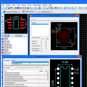
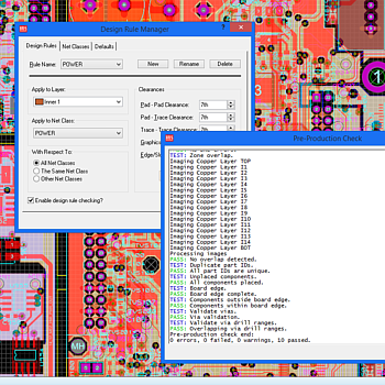
You can place a flood fill with all PCB packages but the ability to place multiple power planes per layer is part of the advanced feature set and requires Proteus PCB Design Level 2 or higher.

Stitching and Shielding

Skjema

Via stitching is a technique used to tie together larger copper areas on different layers, helping keep return paths short and to reduce noise on the PCB. You can automatically stitch planes in Proteus via a simple context menu command. This gives you control over via style and also spacing and row offsets for the stitching pattern.

A via shield or picket fence can be added around the border of the planes in much the same way. This will create a single row of vias around the perimeter of the zones and can help prevent electromagnetic interference with other equipment.

The same technique can be used with high speed routes such as microstrip or stripline to help isolate signals on the PCB operating at different frequencies.

Teardrops

Skjema

Teardrops are often used at the connection point between track and pad to prevent drill breakout during board manufacture. Proteus PCB Design includes comprehensive support for teardrops. When enabled, teardrop connections will be made to all qualifying routes. They are then automatically generated, updated and removed as you place, edit and delete routes during board layout.

Verification

Skjema

During manual routing, Proteus checks each track as you place it and warns you if any design rules (physical/electrical) are broken. You can fully customise the board constraints, setting rules by layer and/or by strategy or even creating rules governing behaviour between strategies on the board.

A live indication of both the connectivity and the design rule status of the board is provided on the status bar at the bottom of Proteus. Clicking on either produces a report listing any missing or extra connections - double click on any entry in the list, and the software will zoom in to show you exactly where the error is located on the PCB.

Finally, the Pre-production check runs prior to manufacturing output and is designed to be an automated quality assurance check. In addition to testing connectivity and design rules it tests power plane geometry and integrity through a completely separate code path and runs separate tests for common design mistakes.

Project Notes

Skjema

Project Notes is an application module in Proteus for adding documentation or written content to the project. It is a free-form editor so you can add whatever you like in whatever style you want. This may be as simple as scribbling a TBD list at the end of the working day or as formal as an approved revision history for the project.

The template system in Project Notes allows you to create, save and re-use formatted content and we have included some example templates for things like Engineering Change Orders, PCB Specifications and Lab Exercises that might prove useful.

In keeping with the other modules in Proteus, you can use Project Notes to interact with the rest of the system. For example, you can link text to real parts on the schematic or layout so that clicking on the link will navigate to the part in your design or PCB. You can also use field codes to bring in design information such as Author or Revision Number and the internal clipboard makes it easy to copy and paste pictures from other Proteus modules into Project Notes.

3D Visualisation

Skjema

The 3D Visualisation Tool (3D Viewer) in Proteus provides a way to extrude a layout and view the board as it would appear in real life. This is extremely useful as a design aid during board layout. Navigation, both orbital and 'fly by' is extremely intuitive and mouse controlled. The user can also specify a 'height plane' corresponding to the board chassis which will appear as a semi-transparent box around the board, allowing for a quick visual check for protrusions.

Proteus libraries come supplied with 3D footprints and comprehensive support for creating custom 3D footprints directly inside Proteus or by importing models via the standard STEP/IGES and 3DS file formats. Files can be exported in these formats from the majority of commercial MCAD packages and there are a large number of free internet resource (e.g. 3dcontentcentral) which have vast libraries of STEP files.

Direct output from the 3D Viewer includes the open source 3ds standard, STEP, IGES, 3D DXF and STL. IDF output is available from the output menu in the layout editor.

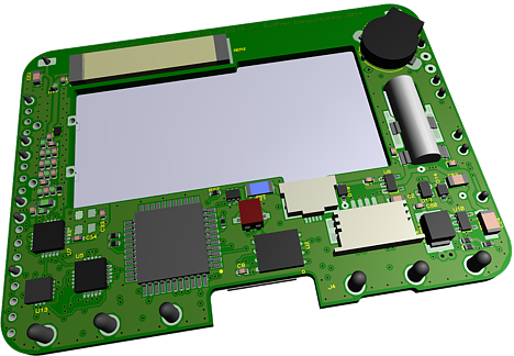
The 3D Viewer, along with its associated import and export formats is part of the Advanced Feature Set and is available only with Proteus PCB Design Level 2 and higher.

Output Formats

Skjema

As well as supporting the basic ability to output your PCB to standard windows printers, Proteus provides a full set of features for professional board manufacturing.

Gerber X2 is the primary supported manufacturing output format. This format, together with an IPC-D-356 netlist and optional assembly drawings, provides an intelligent and complete representation of the PCB to your manufacturer. Traditional Gerber/Excellon output via the RS274X format is also supported.

ODB++ is the secondary supported manufacturing output format. Like Gerber X2, ODB++ is also an intelligent CAD/CAM data exchange format, capturing all CAD/EDA, assembly and PCB fabrication knowledge in one single, unified database.

Finally, you can output to MCAD software like Solidworks directly via the STEP, IGES or IDF file formats.

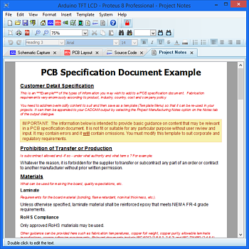
Mechanical CAD output formats such as STEP, IGES, STL and IDF along with the ODB++ advanced manufacturing format are part of the Advanced Feature Set and are limited to the Proteus PCB Design Level 2 and higher.