Schematic Capture

The Proteus schematic capture module lies at the heart of the system, and is far more than just another capture package. It combines a powerful design environment with full support for design re-use and a complete BOM reporting sub-system.

Proteus
Schematic Capture

Making Connection and Wiring Up

Skjema

Placing a wire can be as simple as clicking on the two pins you want to connect - the Wire Auto-Router does the rest. But if you want a wire in a particular place, you can simply click at the intermediate corners. The Wire Auto-Router also operates when components are moved, automatically fixing up the affected wiring.

Buses

Bus

Proteus supports bus wires, terminals, module ports and device pins. This makes it ideal for handling complex microprocessor designs in which some devices may have over 400 physical pins. Tedious editing is avoided by drawing each of the address and data buses as a single pin. Bus terminals and module ports allow bus interconnections between sheets and hierarchy levels to be quickly specified.

Hierarchical Design

Skjema

As well as supporting normal multi-sheet designs (equivalent to a circuit spread over several pieces of paper), Proteus capture fully supports hierarchy within a design. In other words, a particular component can be defined as a module which is then represented by a further circuit diagram. The hierarchy can be nested to an arbitrary number of levels and modules can be drawn either as standard components or a special sub-circuit blocks on which the interface ports can be placed and removed on the fly.

Device Libraries

Bus

Proteus capture comes with pre-supplied libraries for TTL, CMOS, ECL, Microprocessor, Memory and Analogue ICs plus libraries with hundreds of named Bipolar, FET and Diode discrete semiconductors. Also included are manufacturer specific libraries from National Semiconductor, Philips, Motorola, Teccor, Texas Instruments, Dallas and Zetex amongst others - an expanding total, currently well over 35,000 parts. Additional parts can easily be created on the schematic while BSDL import provides a semi-automatic route for creating complex ICs.

Technical brochure (Labcenter)

Packaging Tool

Skjema

Matching schematic and PCB library parts is greatly simplified by the packaging tool. This tool provides a graphical environment in which to assign one or more PCB footprints to a schematic part. For each PCB package, a table mapping pin numbers to pin names is created such that different packagings can have different pin numbers for the same schematic pin.The packaging tool also facilitates the entry of different pin numbers for each element in a multi-element part, and each bit of a bus pin.

Project Clips / Design Snippets

Bus

Project clips or snippets provide a formal way to reuse parts of an existing project in future work. The basic idea is simple; select an area of schematic and/or an area of layout and then export them to disk for import into future project.
You can create schematic only project clips or, more commonly, the project clip will contain both the schematic design and the corresponding pcb layout. When you bring the project clip into a different project and place the schematic the associated pcb clip will be ready for placement as a single unit with the correct annotation. Over time, you can build your own library of useful pieces that can then be re-used in future work.

Assembly Variants

Skjema

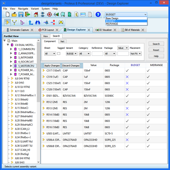
Assembly Variants provide a simple method of managing multiple product configurations in a single schematic/pcb project. This is done by specifying the fitted or not fitted status of each component on a per variant basis.
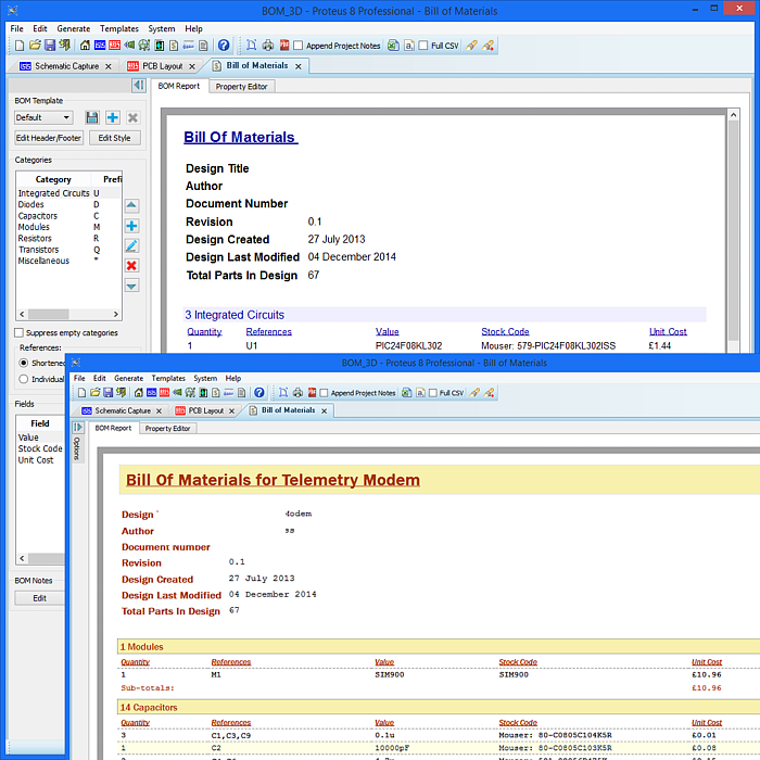
In Proteus, the user interface is managed by the Design Explorer which has a column for each variant, allowing the user to easily add/remove components from that product variant. The software then manages this information through all of the output systems, changing the BOM Report, the Pick and Place files, the Assembly Drawings, the 3D Viewer and any export for MCAD.

Bill of Materials

Bus

The Bill of Materials in Proteus 8 operates in its own application window with a WYSIWYG view of the report. Changes to the schematic and/or formatting are reflected immediately and an integrated header/footer editor is also provided.
Further more, component properties can be added/removed or edited from within the BOM window. Any changes are automatically back-annotated onto the schematic. This is, of course, the most natural place to add stock/order codes, component costs and so forth.
The final output can be to print, Excel or PDF as you wish.

Design Explorer

Skjema

The Design Explorer is a unique tool in Proteus which provides a windows style user interface to allow you to both navigate and inspect your schematic at any stage in the design process. It includes the ability not only to interrogate the current state of the schematic to verify connectivity, packagings etc. but also to navigate to items of interest on both the schematic and the PCB (cross-probing to a PCB footprint or a net in the layout package).